
01
PRIMARY ROUTE
Cable tray / central cable tray
Organize power and data below the desktop or through the center of a facing two-person workstation run.
Review the tray system
PROJECT ACCESSORIES / CABLE MANAGEMENT
Coordinate cable trays, cable spines, destination-ready desktop power, and monitor arms around the workstation layout before production starts.
QUICK ANSWER
Standing desk cable management works best when the tray position, floor drop, desktop power, monitor load, and frame movement are checked together. Adding accessories after installation can create avoidable fit and routing problems.
B&H Ergonomics reviews common project accessories alongside the standing desk frame, desktop plan, workstation quantity, and destination requirements. Final dimensions, finishes, openings, electrical configuration, and compatibility are confirmed in the quotation.
FOUR PROJECT ACCESSORY ROUTES
Product photos shown here are structured placeholders until the approved tray, spine, power module, and monitor arm images are added.
Organize power and data below the desktop or through the center of a facing two-person workstation run.
Guide moving cables between the desktop, central tray, and floor while preserving a controlled path.
Bring local-standard power plus selected USB-A and USB-C charging to the work surface.
Scope single-screen, dual-screen, or monitor-and-laptop configurations against the equipment plan.
Q43 CENTRAL CABLE TRAY
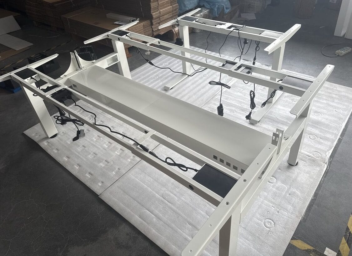
On a BH-Q43RS facing two-person workstation, the central cable tray is fixed to the frame structure and does not rise with either desktop. Each user retains an independent lifting system while shared power and data can stay organized between the workstations.
CABLE SPINE ROUTES
Black and white are the standard colors. Length and routing remain configurable against the project.
The spine connects the desktop cable route to the floor. The standard single-workstation length is 1300 mm and can be configured for the project.
Typical route: desktop to floorWhen a fixed central cable tray is used, the spine connects the tray to the desktop cable path. The standard facing-workstation length is 1200 mm.
Typical route: central tray to desktopPOWER + DATA OPENINGS
Opening size and position should follow the selected power and data connectors, cable direction, tray type, and service access. B&H can review custom openings in the tray or related hardware as part of the project configuration.
Do not rely on a generic opening drawing when the connector model is still undecided. Send the selected component drawing or sample information with the RFQ.
Power outlet, data module, USB assembly, or other selected component.
Width, height, corner radius, tolerance, and fixing method.
Distance from tray edges, cable approach, and installation access.
Openings per workstation and repetition across the full office run.
DESKTOP POWER MODULE
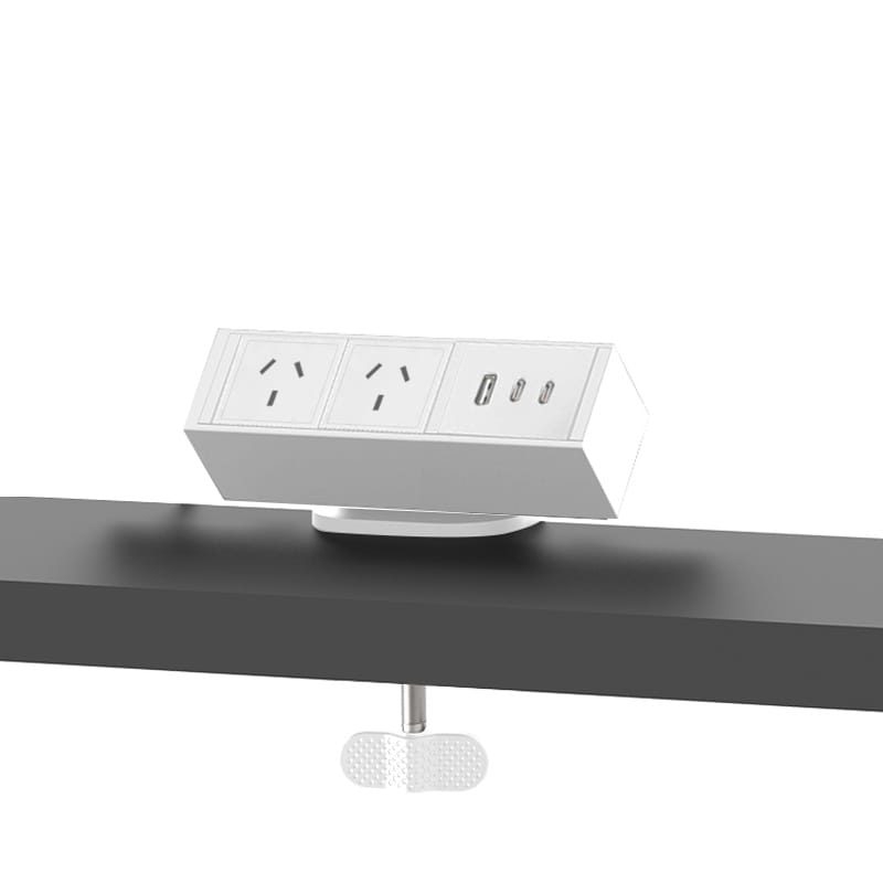
Desktop power can be reviewed with local-standard power outlets, USB-A, and USB-C. Black and white are the common housing colors; other colors can be evaluated against the project.
Compatibility boundary: B&H does not claim that every internal structure, output, or certification is available in every market. Final electrical specifications and compliance documents depend on the destination and selected product.
MONITOR ARM OPTIONS
Monitor arms are produced by a partner factory using B&H-owned tooling. Final fit depends on the selected screen, VESA pattern, weight, desktop, clamp or grommet position, and planned workstation load.
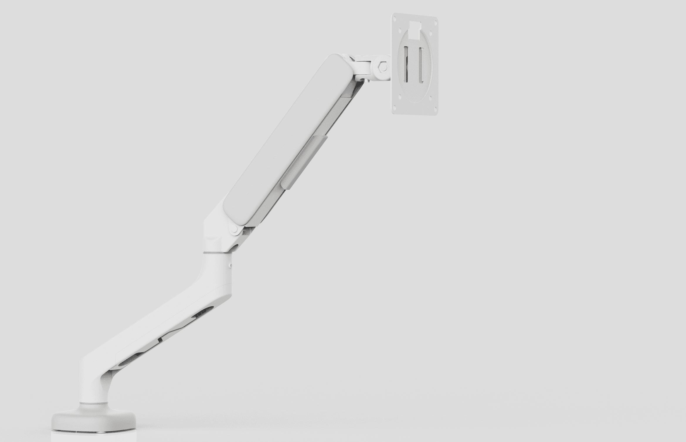
One screen on an independently adjustable arm, checked against the monitor and desktop installation.
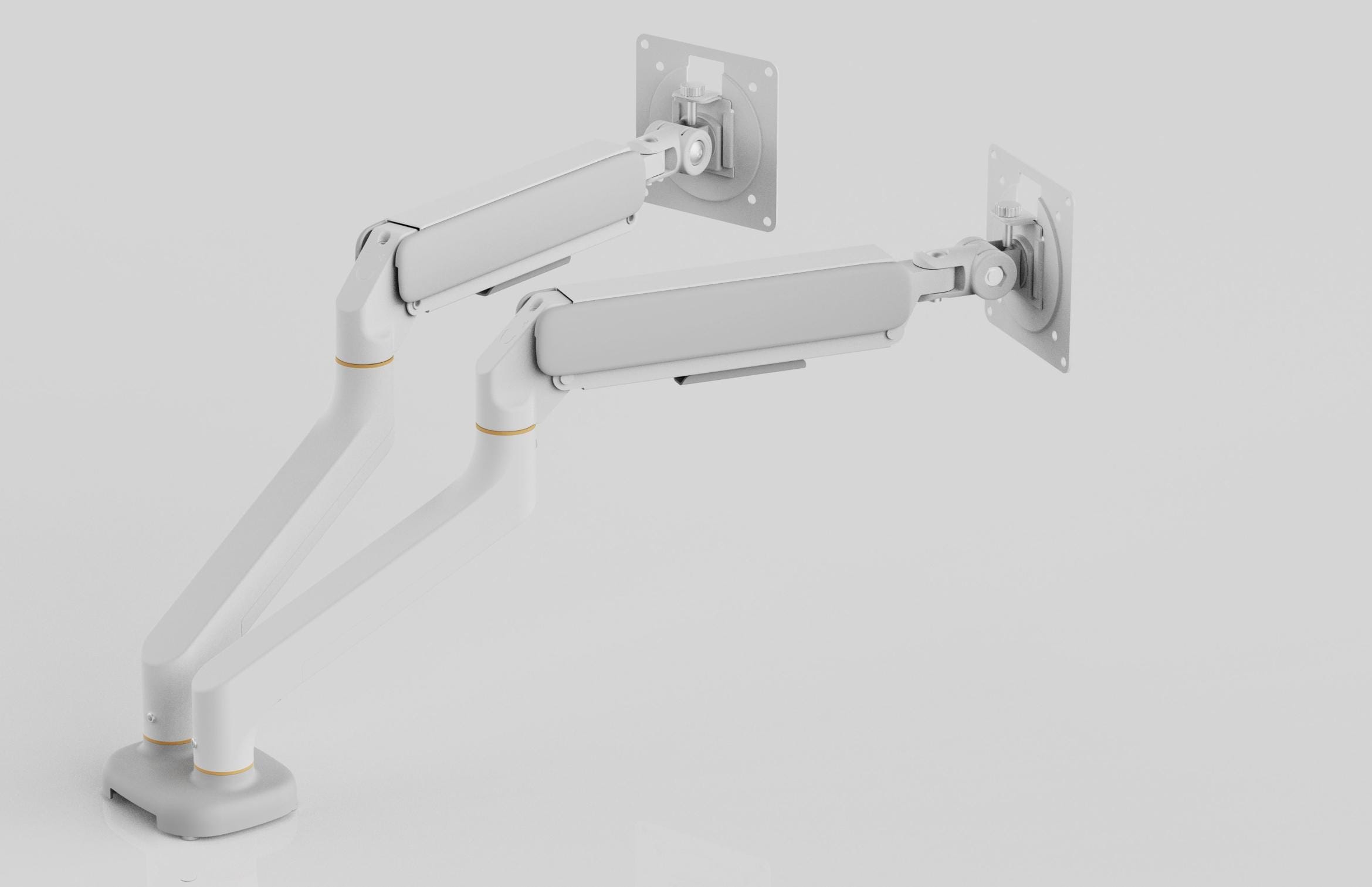
Two screens with final compatibility confirmed from the individual monitor specifications.
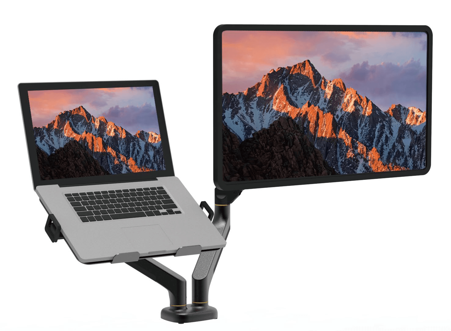
One screen arm paired with a laptop tray when the equipment plan requires a mixed setup.
CONFIGURATION EXAMPLE
This is a scope example, not a fixed bundle or public price package. Select only what the floor plan and workstation standard require.
Select the workstation form, width, height route, load, finish, and quantity.
Choose below-desktop or central routing, adjustable or fixed length, and openings.
Confirm the desktop-to-floor or central-tray-to-desktop route and color.
Add destination-ready desktop power and monitor support when required.
QUOTE-READY ACCESSORY BRIEF
The frame model, layout, accessory scope, electrical market, quantity, and destination are enough to begin the review.
BUYER QUESTIONS
Answers describe the current B&H project route. Final dimensions, compatibility, electrical details, production timing, and delivery terms are confirmed in the quotation.
No. This page supports project procurement rather than consumer retail. Cable management accessories are normally configured with an eligible standing desk frame or office workstation project.
No. The central tray is fixed to the frame structure while the two desktops move independently. Final supports, length, openings, and cable capacity are confirmed for the selected project.
Yes, subject to project and production review. Send the connector model, cutout dimensions, fixing method, opening position, quantity, and layout before the tray is finalized.
The standard single-workstation spine is 1300 mm and the standard facing-workstation spine is 1200 mm. Black and white are standard colors. Other length or routing requirements can be reviewed for the project.
B&H can review local-standard power outlets plus selected USB-A and USB-C options. The exact socket, electrical specification, output, and compliance documents depend on the destination and selected module.
A standalone monitor-arm order has a 500-set MOQ. When monitor arms ship with an eligible standing desk frame project, there is no fixed separate MOQ; the quantity is evaluated with the complete project.
Provide the frame model, workstation layout, desktop dimensions, tray and spine route, connector or power requirements, monitor details, accessory quantities, destination, trade term, and target schedule.
READY FOR AN ACCESSORY REVIEW
B&H replies within 48 business hours with the next configuration or quotation questions.