
Quick Answer
A standing desk mechanism is the system that changes a desk’s height. In a screw-driven electric desk, the motor supplies rotational power, while a screw-and-nut assembly converts that rotation into linear movement inside the lifting column. The telescopic column extends or retracts to move the desktop. A controller manages motor operation in response to the user’s commands.
Last Updated: September 16, 2026 | Author: William | Estimated Reading Time: 7 minutes
What Is a Standing Desk Mechanism?
The mechanism includes the parts that generate, transmit and guide the movement needed to raise or lower a desktop. On an electric desk, those parts work with a power supply, controller and operating panel.
Different desk designs produce that movement in different ways:
- Electric desks use motors to drive a lifting system.
- Hand-crank desks use the person turning the crank to supply mechanical power.
- Gas-spring-assisted desks use a gas spring to help counterbalance the moving load.
For a common screw-driven electric desk, the part hidden inside the leg is central to understanding the movement. “Single motor” and “dual motor” describe the number of motors. Neither phrase explains how their rotation becomes an upward or downward movement.
How Motor Rotation Becomes Vertical Movement
The Motor Supplies Rotational Power
An electric motor turns a shaft. That rotation supplies the mechanical power for the lifting system; the motor shaft does not simply pull the desktop upward.
Depending on the design, the motor sits in a housing near the top of the leg or is integrated into the column. Its output must reach the lifting mechanism through the appropriate drive components.
The Transmission Drives the Screw Mechanism
Gears, couplings and, in a mechanically linked design, a connecting shaft transfer rotation from the motor to the screw drive. A reduction gear changes the relationship between rotational speed and torque before the drive reaches the screw.
The transmission and the screw mechanism have different jobs: the transmission carries and adapts rotation; the screw-and-nut assembly converts it into straight-line movement. A shaft running between two legs transfers rotation across the frame. It should not be confused with the threaded lifting screw inside a column.
The Screw and Nut Produce Linear Movement
A lead screw is a threaded shaft. A matching nut engages with that thread. In a rotating-screw arrangement, the nut is restrained from turning with the screw, so it travels along the shaft as the screw rotates. Its connection to the moving structure turns that travel into extension or retraction.
Picture a nut on a threaded bolt: if the bolt turns while the nut is prevented from turning, the nut moves along the thread. A lifting column uses that relationship in an assembly designed to carry load and guide travel. The screw’s lead is the axial distance travelled in one relative revolution; it is one reason motor speed alone does not tell you the desktop’s speed.
This is the conversion described in LINAK’s explanation of how a linear actuator works: motor rotation drives a lead screw, and the nut’s movement along the thread creates linear motion.
Reversing the drive reverses the direction of travel. The internal arrangement can differ between lifting-column designs, especially those with multiple telescoping sections, but the key distinction remains: the motor provides rotation; the screw mechanism converts it into linear movement.
The Telescopic Column Guides and Supports the Travel
The visible desk leg consists of nested sections that slide relative to one another. These sections guide the movement and form part of the structure supporting the desktop. The drive mechanism works inside this assembly.
Two-stage and three-stage describe the telescopic column construction, not the number of motors. LINAK’s lifting-column overview distinguishes both constructions and describes motor-housing and inline layouts. A column’s actual minimum height and travel must still be checked in its dimensions.
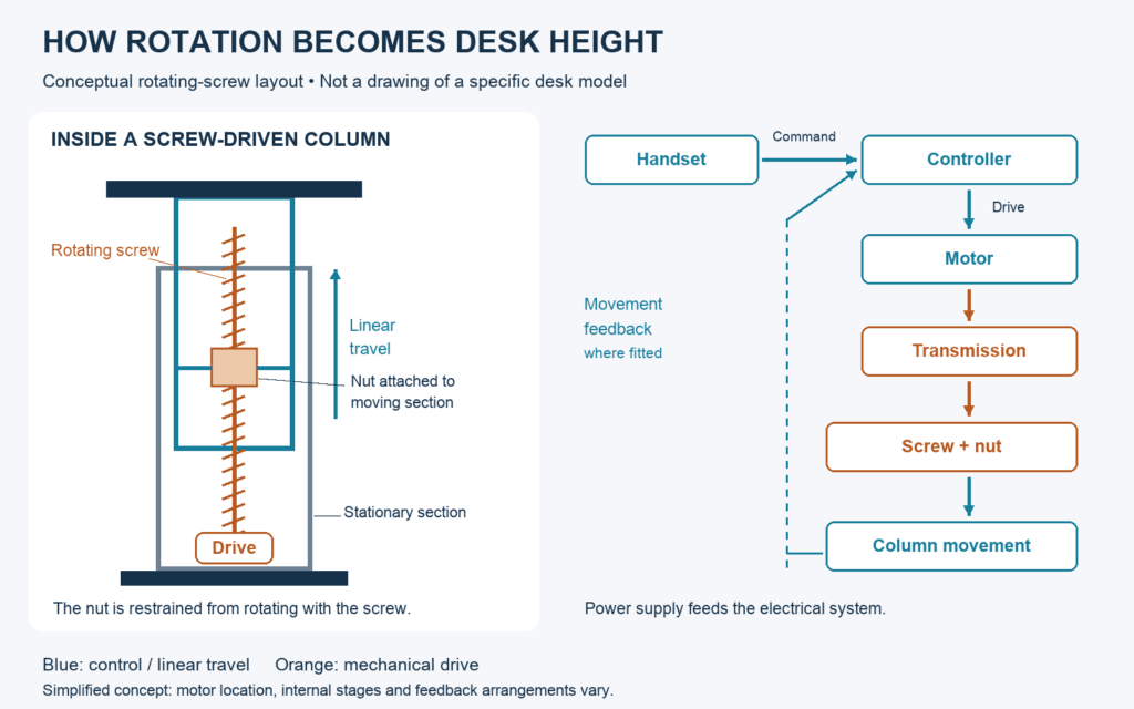
Conceptual rotating-screw layout; component positions and internal arrangements vary by design.
The mechanical sequence is:
Motor rotation → transmission → screw-and-nut movement → column extension or retraction → desktop height change.
That sequence explains motion. It does not establish the load a particular desk can lift or how firmly it holds its position when stopped; those are properties of the complete design.
How the Controller Coordinates the System
The operating panel and the controller perform different functions. The panel is the interface you touch. The controller manages motor operation after receiving that input. In some systems, the electronics are integrated into the lifting assembly instead of housed in a separate box.
During a height adjustment:
- You press an up or down control, or select a saved position where that feature is supported.
- The controller commands the motor drive to run in the required direction.
- The motors and mechanical drive move the lifting columns.
- In a system with movement feedback, the controller uses that information to manage travel and coordinate the driven columns.
- Movement stops according to the operating mode, target position, travel limit or detected fault.
For a two-motor desk, both sides need coordinated movement. Sending power to two motors is only part of that task: the controller, feedback arrangement and matched lifting components determine how the system manages their travel.
LINAK’s control-box explanation identifies power management, movement commands, synchronisation and input connections as control-system functions. The exact functions available depend on the selected hardware and software.
Memory positions, soft start and stop, and anti-collision are therefore features to verify for the desk configuration. A memory handset alone does not establish that every other function is present. Where anti-collision is offered, check the manufacturer’s description of its detection method and limits; keep the desk’s travel area clear.
What Changes Between Single-Motor and Dual-Motor Designs?
In a mechanically linked single-motor layout, one motor transfers rotation to the lifting mechanisms in both legs through a connecting drive shaft. The mechanical connection coordinates their movement.
A documented example is the VIVO DESK-V100EBY series. Its official assembly manual lists a motorized leg and a separate sync rod. Pages 10–11 show the rod connecting the two legs and require the legs to be at the same height during assembly. This shows why mechanical linkage and initial alignment both matter; those instructions apply to that model.
In a dual-motor layout with one motor per leg, each motor drives its own lifting mechanism, while the control system coordinates the two sides. Both layouts can use screw drives inside the columns.
B&H Ergonomics’ BH-D23RS product description identifies a dedicated motor in each leg and three-stage columns. Those are separate attributes: two motors describe the drive layout; three stages describe the nested column sections. The description does not, by itself, establish the internal screw geometry or feedback method.
| Layout | How power reaches the legs | What coordinates movement |
|---|---|---|
| Mechanically linked single-motor design | One motor drives both lifting mechanisms through a mechanical linkage | The linked drive arrangement |
| Dual-motor design with one motor per leg | Each motor drives its own lifting mechanism | The matched motor-control and feedback system |
These examples explain two ways to distribute the drive; confirm the actual layout in the desk’s assembly documentation. The motor count alone does not establish lifting capacity, travel speed or stability. A dual-motor desk still needs suitable transmissions, screw drives, columns and controls working as a complete system.
Synchronization keeps the driven sides travelling together. Stability describes how the complete desk resists unwanted movement at a given height and load. They are related to different parts of the design, so a synchronized lift is not proof of a particular wobble resistance.
What the Mechanism Tells You—and What the Specification Sheet Must Confirm
Understanding the mechanism helps you read a specification sheet without asking one component to explain the whole desk.
| Part or system | Its role | What to confirm for the desk you are considering |
|---|---|---|
| Motor and transmission | Supply and transfer rotational power | Motor layout, lifting speed at the stated load, and permitted operating cycle |
| Screw drive | Convert rotation into linear movement | Rated lifting and holding performance for the assembled system |
| Telescopic columns | Guide travel and support the moving structure | Minimum and maximum height, stroke, and stage count |
| Controller and feedback | Manage operation and coordinate driven columns | Supported column configuration, travel limits, reset procedure and available protection functions |
| Frame, feet and desktop connections | Form the complete workstation structure | Compatible desktop dimensions and evidence for stability at the intended working height |
When comparing load ratings, ask whether the figure applies during lifting or only while stationary, and whether the desktop’s weight is included. When comparing speeds, check the load used for the measurement. For height ranges, distinguish frame height from the finished desktop height.
Use those requirements to compare B&H Ergonomics’ electric standing desk frames and request the specification for the configuration you intend to order. Record the motor layout, column range, lifting load and control functions together. That gives you a clearer basis for selection than “single motor” or “dual motor” on its own.